BLDC Motor Driver 9-24V - 3A
- Availability: Directly available from warehouse in Eindhoven
- SKU: 006519
€21.50
Ex Tax: €17.77
Your shopping cart is empty!


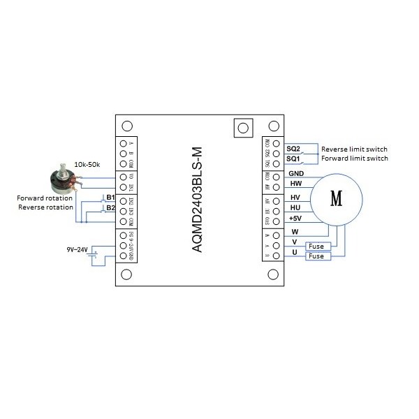
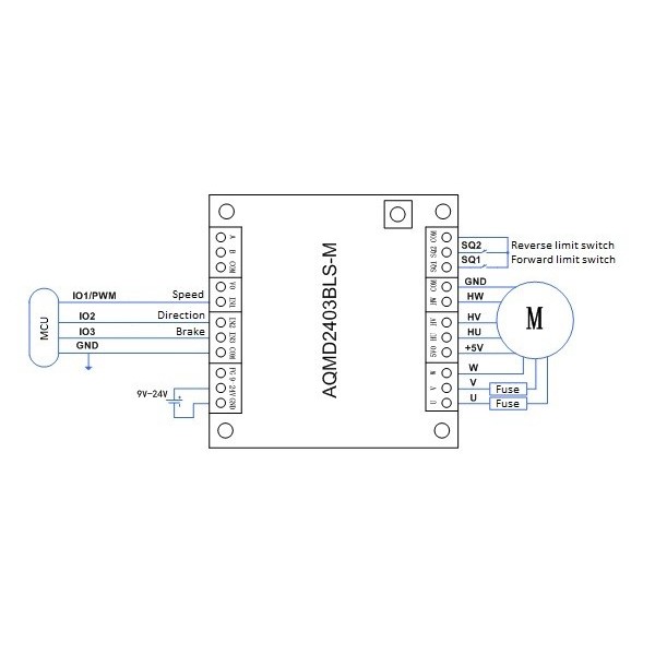
A versatile driver for a brushless DC (BLDC) motor with built-in hall-effect sensors. The driver offers various control methods including via a potentiometer (10kΩ-50kΩ), a microcontroller with PWM and RS485. Many settings (including maximum current, speed, PID settings, etc.) can be adjusted via RS485 and the configuration program for Windows (can be found under the tab "Downloads"). If you do not use this, the driver is set to the maximum settings for speed and current by default.
A complete (translated version) of the datasheet/user manual and the RS485 protocol can be found under the tab "Downloads". See below for a brief version.
Functions of push button and LEDs:
To quickly start with the configuration program (and to test the motor), the following steps can be followed:
Follow the instructions below to test the motor via the configuration program:
Check the tab "Downloads" for more information and/or downloads.
Datasheet: 006519_AQMD2403BLS-M_UM_V0.90.zh-CN.en.pdf
Software: 006519_AQMDBLS_AxBx_Demo_EN.zip
| General | |
| Brand | Akelc |
| Manufacturer model/SKU | AQMD2403BLS-M |
| Minimum operating temperature [°C] | -30 |
| Maximum operating temperature [°C] | 70 |
| Features | Motor driver Current sensor Voltage sensor |
| General physical appearance | |
| Main color | Green |
| Weight [g] | 20 |
| Dimension X [mm] | 45 |
| Dimension Y [mm] | 45 |
| Mounting options | Mounting hole(s) |
| Diameter mounting hole(s) [mm] | 3 |
| Form factor | Module (general) |
| General electrical properties | |
| Minimum supply voltage [V DC] | 9 |
| Maximum supply voltage [V DC] | 24 |
| Minimum IO-pin input voltage [V] | 2 (default but is adjustable) |
| Maximum IO-pin input voltage [V] | 5 |
| IO-pin output voltage [V] | 3.3 |
| Communication | |
| Hardware interface(s) | Analog PWM Digital RS485 |
| Isolated communication | No |
| Default baudrate | 9600 |
| Motor driver | |
| Type | Driver |
| Supported motor type(s) | Brushless DC motor |
| Direction of rotation | Bi-directional |
| Number of brushless DC motor channels | 1 |
| Minimum motor supply voltage [V DC] | 9 |
| Maximum motor supply voltage [V DC] | 24 |
| Motor voltage [V DC] | Equal to motor supply voltage |
| Hall-effect sensor voltage [V DC] | 5 |
| Maximum continuous RMS current per phase [A] | 3 |
| Maximum peak current per phase [A] | 4 |
| Current limiter | Yes, adjustable |
| Safety features | Temperature Overvoltage Undervoltage Overcurrent |
| Connectors | |
| Power supply connector(s) | Screw terminal |
| IO-connector(s) | Screw terminal |
| Motor connector(s) | Screw terminal |
| Package contents | |
| Package contents | 1x Motor driver |