Menu
Your Cart

Due to Ascension Day, we will be closed on Thursday, 29-05-2025.

SK6812 Digital 5050 RGBW LED Strip - 30 LEDs 1m

SK6812 Digital 5050 RGBW LED Strip - 30 LEDs 1m
  • Availability: Directly available from warehouse in Eindhoven
  • SKU: 003069
€10.00
Ex Tax: €8.26

This product is a SK6812 RGBW LED Strip with 30 LEDs on 1 meter. This LED strip has an extra white LED in each module for better white color reproduction. Each LED can be cut separately from the LED Strip. This way you can shorten or extend the LED strip. Underneath the LEDs there is double-sided tape to mount the strip.

The color of the LED is controlled by the built-in chip. You can place a lot of these LEDs behind each other and control them digitally with just 1 pin. The LED strip is powered with 5V.

You can place up to 1024 LEDs in succession and then still achieve 30fps (30 changes per second).
The LED is of the RGB+W type with which each color can be controlled with 8 bits. This allows each LED to display 4294967296 types of colors (32 bits).

Various platforms offer support for this LED with the help of libraries, including Arduino.
More information for the Arduino platform can be found here: Adafruit NeoPixel Überguide.

Meaning of the color of the wires:

  • Red: +5V input voltage
  • Green: Input of data signal (signal from an Arduino, RPi, or other SK6812 RGBW LED)
  • White: Ground/min

Dimensions: 10x2x1000mm

The datasheet of the LED can be found under the tab "Downloads" (LED version: "Naturel White").

This product is supplied in parts of 1 meter, with each meter of LED Strip in a separate package.
You can then attach these LED strips to each other by clicking the connectors together at the ends of the strips.
If you want the strips to be close together, you have to solder them together yourself.

Note: The LED strip has a power of 0.25W per LED module (50mA@5V) regardless of the color. So, a LED strip of 30 LEDs draws around 1.5A. You should take this into account when powering the LED strip.

Note: Make sure that the LED strip on the meter gives an "extra" 5V voltage. This is because the voltage drops over the strip and the current at the start can rise quite nicely (and perhaps the start of your LED strip burns out!).
You can read more about this here: Powering Neopixels.

Check the tab "Downloads" for more information and/or downloads.

Please login or register to review

Reviews Over SK6812 Digital 5050 RGBW LED Strip - 30 LEDs 1m

This product has 0 review(s) in total.

Product FAQ

Use a stable, CE-approved power supply with the correct voltage that can supply sufficient current. The maximum current that an LED can draw is indicated on the product page. Multiply this number by the number of LEDs to calculate the total maximum current. This maximum current is the minimum current that the power supply must be able to supply.

Supplies:

The following components are required to operate a product with digital LEDs:

  • Stable (CE-approved*) power supply that supplies the same supply voltage as indicated in the product specifications above and that can also deliver at least the maximum current that the strip draws (also found in the product specifications). If you use several strips in a row, multiply the number of LEDs by the current that a single LED draws to calculate the minimum supply current.
  • Development board for the control (Arduino, ESP32, Raspberry Pi, or similar).
  • Resistor (470Ω) to stabilize the data line (two if the LED chip also has a clock-pin).
  • Electrolytic capacitor (e.g. 1000μF 25V) as a buffer for peak currents.
  • Wires or cables to connect everything. Make sure that the power cables can handle the current that the strip/matrix draws.

The following parts are optional:

  • Breadboard or experimental circuit board to attach components
  • Level converter (if the development board has a signal voltage of 3.3V)

Connecting the strip:

  1. Turn off the power before continuing.
  2. Connect the wires (wire color is indicated on the package):
    1. First, connect the GND (ground/min) of the LED strip to GND of the power supply (also disconnect this last when disconnecting the strip).
    2. Connect the data (DI) wire through a 470Ω resistor to the signal pin of the development board (a level converter may be needed for 3.3V development boards).
    3. If the strip/matrix has a backup data line (WS2813/WS2815/etc.): Connect the backup data line (BI) to GND, or to the backup data out (BO) wire of another strip/matrix.
    4. If the strip/matrix has a clock pin (APA102/NS107S/etc.): Connect the clock pin via a 470Ω resistor to a signal pin of the development board (a level converter may be required for 3.3V development boards).
    5. Connect the power supply wire to the positive of the power supply.
  3. Connect the GND of the strip and power supply to the GND of the development board.
  4. In case of several strips/matrices in a row: Connect an extra external power cable between each meter of LED strip.
  5. Place the large capacitor (1000μF 25V) between GND and the power wire, near the beginning of the strip/matrix.
  6. The power supply can now be switched on. Please note that the LEDs only light up when the development board gives a correct control signal.

*There are many power supplies on the market that have a China Export ("fake" CE marking) or carry a CE marking, but are in reality not CE approved. We do not recommend using these, often cheap (Chinese), power supplies because they generally do not provide a stable voltage. A stable voltage is essential to make the LEDS work stable, and to prevent damaging them.

More information:

We recommend reading the following pages for more information (especially when using multiple LED strips): Powering Neopixels and Adafruit NeoPixel Überguide.

This can have several causes. The most common causes are:

Signal voltage too low
For example, WS2812B LEDs have a signal voltage of 5V. When these are controlled with a voltage of 3.3V (as with ESP32/ESP8266/Raspberry Pi), data may not be properly received at one or more LEDs, resulting in the wrong color. This can be solved by increasing the signal voltage to 5V using a level converter.

Noise on the signal pin
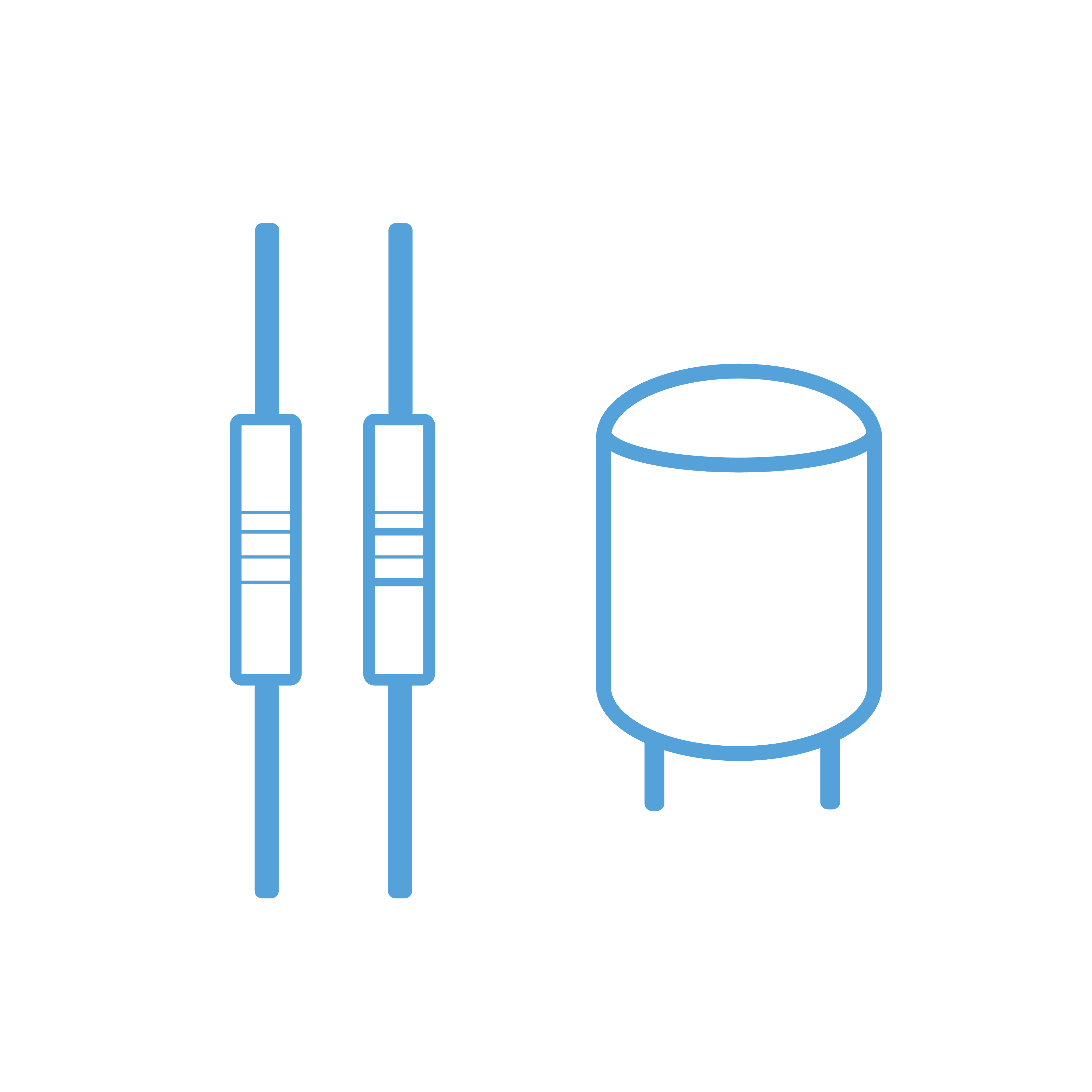
The signal pin is sensitive to noise. This can be solved by connecting a 470Ω resistor in series between the microcontroller and the signal pin of the LEDs.

Voltage drop in supply voltage
Particularly with many LEDs in succession, it can happen that a part does not display the right color. This may be a sign that the supply voltage has dropped too far due to losses in the cabling. This can be solved by using extra thick power cables and connecting them between each strip.

If you have a question or problem regarding a product, please contact us by using one of the buttons below.

1
false
true
true
Remove
Change
tr